
Views: 0 Author: Site Editor Publish Time: 2026-06-12 Origin: Site


Standard electric motors inherently spin at incredible speeds. They naturally produce high-speed, low-torque output. Attempting to force a standard motor to run at low speeds to drive heavy loads creates immediate problems. It causes the motor to stall, overheat, and eventually suffer premature failure. Engineers solve this mechanical mismatch by specifying a Reduction Gear Motor. This integrated power transmission assembly couples an electric motor directly to a gear reducer. It multiplies mechanical turning force while simultaneously decreasing the output shaft speed to practical levels.
Proper implementation goes far beyond understanding a basic mechanical definition. You must carefully match gear topologies, exact reduction ratios, and physical load capacities to specific industrial applications. In this guide, we explore how different mechanical layouts handle operational stress. You will learn how to calculate proper torque requirements accurately. We will also cover environmental variables to help you avoid unexpected failures and ensure your equipment runs efficiently.
A reduction gear motor physically couples a motor and gearbox to trade rotational speed (RPM) for mechanical turning force (torque).
Selecting the correct unit requires calculating the exact reduction ratio, factoring in mechanical efficiency losses (typically 60-95% depending on gear type).
Different gear topologies (planetary, worm, spur) serve distinct operational requirements regarding space constraints, backlash tolerance, and cost.
Evaluating duty cycle and radial/axial shaft loads prevents over-specifying or under-powering the application.
To specify automation components correctly, you must first understand the fundamental physics governing power transmission. Electric motors generate mechanical power. We calculate this power by multiplying rotational speed by torque. Because the total input power remains relatively constant, altering one variable forces an inverse reaction in the other.
The core mechanical principle relies on gear reduction to decrease the motor output RPM. As the speed drops, torque increases proportionally. Think of a bicycle shifting into a lower gear to climb a steep hill. The pedals turn faster, but they deliver more climbing force to the rear wheel. In industrial machinery, a 10:1 reduction ratio means the output shaft spins ten times slower than the motor shaft. Consequently, it delivers roughly ten times the turning force to the load.
Purchasing a pre-integrated assembly offers significant structural advantages over sourcing a separate motor and standalone gearbox. Factory-integrated units guarantee perfectly aligned mechanical tolerances. This precision eliminates the need for external couplings. Eliminating couplings removes a common point of mechanical failure. Integrated units also require a much smaller physical footprint. They streamline machine design and offer the security of a single-source manufacturer warranty. You avoid disputes between different component suppliers if a failure occurs.
No mechanical power transmission system achieves perfect efficiency. Gearing generates friction. Bearings create drag. Lubricants introduce viscous resistance. These factors convert a portion of the input power into waste heat. You must account for these transmission efficiency losses in your final torque calculations. If you ignore efficiency ratings, you risk severely under-powering your machine.
Gear Topology | Typical Transmission Efficiency | Primary Friction Source |
|---|---|---|
Spur Gear | 90% - 95% | Rolling friction at gear teeth |
Planetary Gear | 80% - 90% | Multiple meshing points |
Worm Gear | 50% - 70% | High sliding friction along the worm shaft |
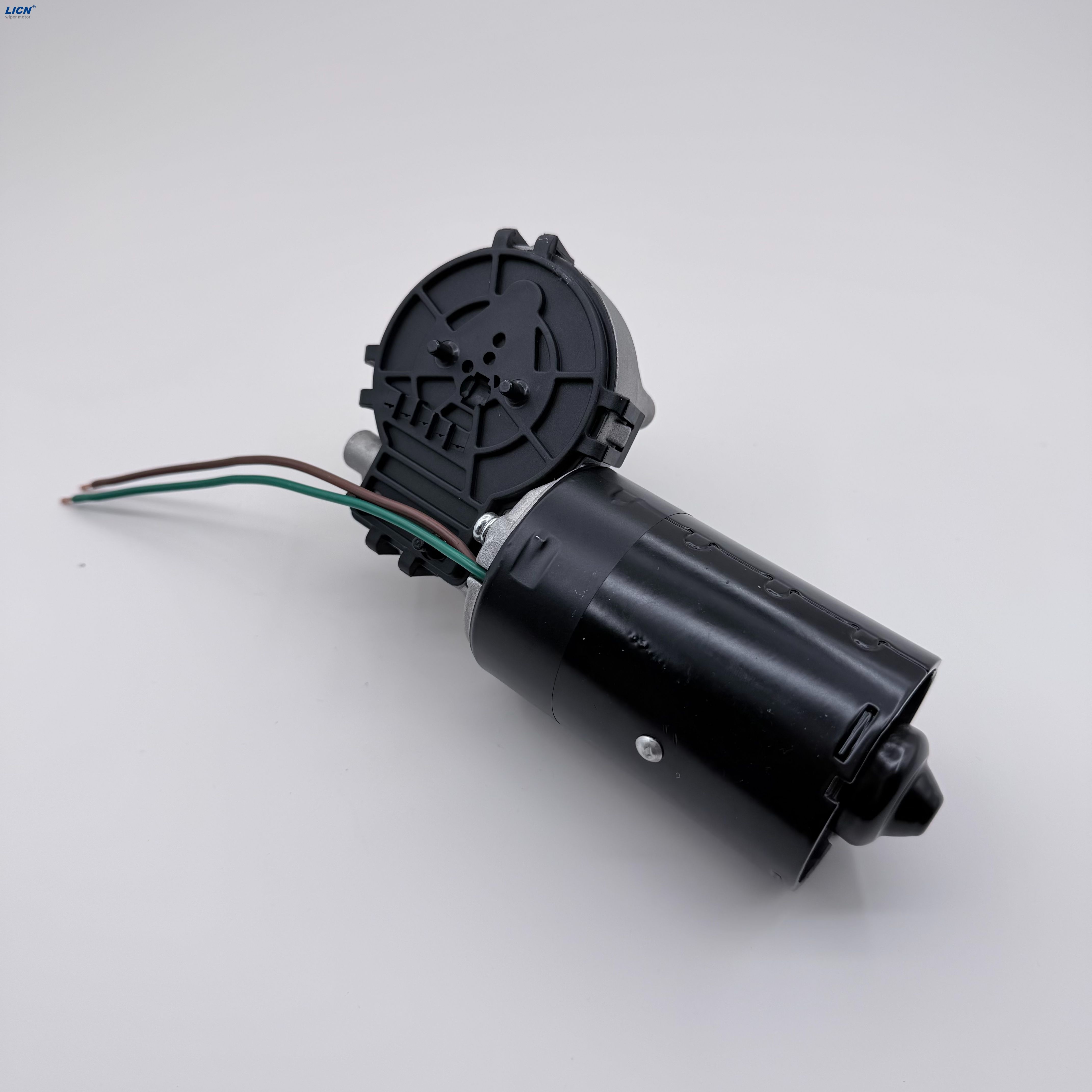
Engineers design different gear arrangements to solve unique mechanical challenges. The internal layout dictates how the unit handles shock loads, fits into tight spaces, and impacts your project budget. Selecting the right Gear Motor topology ensures long-term reliability.
Planetary systems feature a central sun gear driving multiple planet gears. These planet gears rotate inside a stationary outer ring gear. This design distributes the load across multiple contact points simultaneously.
Strengths: They deliver exceptional torque density. They offer a compact cylindrical footprint. The coaxial shaft alignment simplifies machine design. Load distribution across multiple gears handles shock forces beautifully.
Use Case: They dominate precision robotics, heavy-duty industrial automation, and highly space-constrained applications.
Spur gearboxes utilize straight-cut gears mounted on parallel shafts. It represents the most traditional and straightforward approach to speed reduction.
Strengths: They remain highly cost-effective. They boast excellent transmission efficiency. The simple internal layout makes maintenance straightforward.
Limitations: They possess a lower maximum torque threshold compared to planetary units. The offset output shaft complicates direct inline mounting. They also generate higher acoustic noise at high operational speeds.
Use Case: Engineers frequently specify them for conveyor belts, standard material handling systems, and basic commercial appliances.
A worm gear system uses a threaded screw-like shaft turning against a toothed wheel. This unique geometry transfers power at a right angle.
Strengths: The right-angle output saves immense space in tight machinery cabinets. More importantly, high-ratio worm gears are inherently self-locking. They act as a mechanical brake when power shuts off. The load cannot back-drive the motor.
Limitations: The sliding action creates massive friction. This friction results in lower efficiency ratings. They generate significant heat during continuous operation.
Use Case: They excel in hoists, vertical lifts, and any application requiring fail-safe positioning holding.
Guessing motor specifications leads to expensive field failures. You must rely on precise math to match the power source to the physical load. Follow established engineering formulas to guarantee success.
You must work backward from the required speed of your application to determine the necessary input-to-output reduction ratio. Follow these steps to establish your baseline:
Define the exact linear or rotational speed your final mechanism requires to function.
Identify the base operating speed of the electric motor (e.g., 1800 RPM or 3000 RPM).
Divide the motor speed by the target application speed.
Select the closest standard gear ratio available from the manufacturer catalog (e.g., 30:1 or 100:1).
Many procurement specialists mistakenly size units based only on running torque. You must differentiate between continuous torque and peak torque. Continuous torque represents the force required to keep a stable load moving at a constant speed. Peak torque represents the brief, massive surge of force required to overcome static inertia during startup. It also represents the force needed to clear sudden mechanical jams. Always verify the gearbox can survive the application's peak torque spikes without shearing its internal teeth.
Industrial standards dictate the use of a "Service Factor" multiplier to prevent premature gear wear. The American Gear Manufacturers Association (AGMA) provides guidelines for these calculations. If your machine runs 24 hours a day under heavy shock loads, a basic motor will fail quickly. You apply a Service Factor multiplier to your baseline torque calculation. A uniform load running 8 hours a day might use a 1.0 multiplier. A rock crusher running continuously might require a 2.0 or higher multiplier. This ensures you purchase a physically more robust gearbox capable of surviving harsh realities.
A perfectly sized motor will still self-destruct if you ignore the physical environment and the external mechanical forces acting upon the output shaft.
You must carefully guide buyers to verify the overhung load capacity of the output shaft. External attachments exert destructive forces on internal bearings. Radial loads push sideways against the shaft. Belts, chains, and pulleys create immense radial tension. Axial loads push or pull directly in line with the shaft. Lead screws and augers generate heavy thrust loads. Failure to account for these side-loads or thrust loads quickly destroys motor bearings and compromises internal oil seals.
You must actively manage the risk of overheating. Motors generate heat, and confined enclosures trap it. Match the motor design to the application's true duty cycle using standard IEC classifications. An S1 duty cycle rating means the motor can run continuously without exceeding its thermal limits. An S3 rating denotes intermittent periodic duty. If you force an S3 motor to run continuously, the internal insulation will melt, causing a catastrophic electrical short.
Evaluate exact environmental exposure before purchasing. Specify IP54 or IP65 requirements for environments filled with airborne dust and splashing water. Food processing facilities often demand IP69K ratings to survive high-pressure, high-temperature chemical washdowns. Additionally, you must note CE or UL compliance necessities. Commercial integration often requires these certifications to satisfy local electrical codes and corporate insurance policies.
Once you define the technical parameters, you face critical procurement decisions. The sourcing strategy dictates your project timeline and ultimate design flexibility.
You need a reliable framework for deciding between catalog models and custom-engineered solutions. Off-the-shelf units offer significantly faster lead times. They utilize standardized mounting faces and provide proven reliability data based on thousands of field installations. They perfectly suit rapid prototyping and low-volume production. Custom-engineered solutions provide the exact OEM fit your machine requires. Engineers can tweak winding specifications, alter shaft dimensions, and specify unique lubricants. However, custom designs demand higher minimum order quantities and longer engineering lead times.
Take immediate action to secure the right components for your project. Before you request CAD models or consult a manufacturer’s application engineer, document your exact parameters. Record your available input voltage. Note the required target RPM. Calculate your continuous and peak torque loads. Measure the maximum allowable physical envelope size. Having this data prepared ensures you receive accurate technical support and prevents costly redesigns late in the development cycle.
Specifying the right power transmission component is an exercise in balancing torque requirements against physical footprint limitations and efficiency goals.
Always account for mechanical friction losses and external radial or axial forces acting on the output shaft.
Never guess your mechanical parameters; apply rigorous mathematical load calculations using established industry service factors.
Prioritize active collaboration with manufacturer application engineers over buying components strictly based on the lowest initial price point.
A: Higher reduction ratios require more internal gear stages. Each additional stage introduces more points of potential mechanical wear. However, a high ratio effectively protects the electric motor from severe high-amperage strain. It allows the motor to spin freely at its optimal speed. Proper lubrication and adhering to strict service factors ensure long lifespans regardless of the ratio.
A: Yes, most configurations handle reverse operation easily by switching the electrical polarity. However, high-ratio worm gear motors often cannot be back-driven mechanically by the load. Their inherent sliding friction geometry makes them self-locking. This creates a highly effective natural brake, but it prevents manual reversing if the power fails.
A: Exceeding the maximum torque rating causes immediate catastrophic failure. You will experience stripped gear teeth, sheared output shafts, or complete electrical motor burnout due to stalling. Engineers must design safeguards into the machine. We strongly recommend utilizing mechanical slip clutches or implementing electronic torque limits within the motor controller.


