Views: 0 Author: Site Editor Publish Time: 2026-01-26 Origin: Site


The question of whether a gear motor can adjust speed is one of the most common inquiries in industrial drive design. The short answer is nuanced: the gearbox component typically provides a fixed mechanical reduction ratio, stepping down speed permanently by a specific factor. However, the motor component can often be adjusted dynamically through external controllers, effectively changing the output of the entire system. Understanding this distinction is critical for engineers and procurement managers trying to balance performance with cost.
In a business context, this solves a core engineering challenge: achieving high torque at low speeds without destroying the equipment. Running a standard motor slowly to achieve low output speed often leads to overheating and burnout. Conversely, buying a massive direct-drive motor to handle the torque requirement is usually cost-prohibitive. We use reduction strategies to bridge this gap. This article explores the technical differences between fixed mechanical reduction and variable electronic control, helping you select the right Reduction Gear Motor architecture for your specific application.
Fixed vs. Dynamic: Gearboxes shift the operating range of a motor; they do not dynamically adjust speed on the fly without a Variable Frequency Drive (VFD) or DC controller.
Torque Multiplier: Speed reduction is the "cost" paid to gain mechanical advantage (torque), allowing smaller, cheaper motors to drive heavy loads.
Thermal Efficiency: Using a gearbox allows the motor to run at its optimal high-speed efficiency curve (reducing $I^2R$ heat losses) while the load moves slowly.
The "Build vs. Buy" Decision: Integrated gear motors often reduce engineering TCO compared to sourcing separate motors and reducers.
To understand speed adjustment, we must first decouple the "gear" from the "motor." A standard industrial gear motor is a unified system, but its two main components perform very different physical tasks. The gearbox acts as a strict mathematical constant, while the motor acts as the variable potential.
The gear reducer operates on fixed physics. It acts as a mechanical constant defined by the number of teeth on its internal gears. If you select a gearbox with a 10:1 reduction ratio, it will always divide the input speed by exactly 10. It cannot decide to divide by 5 or 20 on the fly. This mechanical rigidity is a feature, not a bug, for many applications.
For decision-makers, this presents a clear pivot point. If your conveyor belt or pump requires a single, constant low speed—for example, moving material at exactly 0.5 meters per second continuously—a fixed-speed AC induction Gear Motor is likely your most reliable and cost-effective choice. You select the ratio that matches your mains frequency (50Hz or 60Hz) to your desired output, and the machine runs indefinitely without complex electronics.
When an application requires variable speed, the adjustment does not happen inside the standard gearbox. It happens at the electrical input stage of the motor. The gearbox simply scales whatever speed the motor provides.
For DC motors, speed is typically adjusted via voltage regulation or Pulse Width Modulation (PWM). By "chopping" the power supply rapidly, the controller effectively lowers the average voltage seen by the motor, causing it to slow down. For AC motors, we use a Variable Frequency Drive (VFD). The VFD changes the frequency (Hz) of the electricity entering the motor. If you drop the frequency from 60Hz to 30Hz, the motor spins at half speed. Consequently, the output shaft of the gear motor also turns at half speed.
It is vital to view the "Gear Motor" as a coupled unit. To adjust its speed, you are fundamentally adjusting the motor's behavior. The gearbox is merely a passive multiplier that translates that adjustment into usable torque. If you need a system that can ramp up, slow down, or hold position, you must spec a motor capable of variable control and pair it with the correct electronic drive.
A common question from non-engineering stakeholders is: "Why do we need a gearbox at all? Can't we just apply less voltage to the motor so it spins slowly?" While theoretically possible, this approach creates significant efficiency and thermal risks in industrial environments.
There is a severe engineering risk associated with running a standard motor at very low RPMs to achieve low speed without mechanical gears. Physics dictates that to move a load, you need torque. In an electric motor, torque is directly proportional to current (Amps).
If you try to drive a heavy load at 50 RPM using a direct-drive motor, that motor must draw massive amounts of current to generate the necessary magnetic field. This leads to Resistive Heating, often called "Copper Loss" ($I^2R$ losses). Because the motor is barely turning, its internal cooling fan is also ineffective. The result is a motor that draws high amperage, produces excessive heat, and likely burns out its insulation classes rapidly.
From a Total Cost of Ownership (TCO) and longevity perspective, motors have a "happy range." Most standard industrial motors are designed to operate most efficiently at high speeds, typically between 1,500 and 3,000 RPM. At these speeds, the cooling fan moves sufficient air, and the magnetic interaction is optimized.
Using a reduction gear motor allows you to keep the motor in this happy range. The motor spins fast (staying cool and efficient), while the gearbox mechanically reduces that speed to the slow RPM required by your application. This separation of duties is the primary reason gear motors remain ubiquitous in automation.
Consider the physical footprint. To generate 100 Nm of torque at 60 RPM without a gearbox, you would need a physically massive direct-drive motor with large copper windings. By using a 30:1 gearbox, you can use a tiny motor spinning at 1,800 RPM to achieve the same 100 Nm output. This results in a smaller machine footprint, lower weight, and significantly lower energy consumption for the same work output.
Once you determine that a reduction gear motor is necessary, you must choose the architecture that best fits your speed control needs. Here are the three most common setups found in modern manufacturing.
| Architecture | Best For | Primary Advantage | Primary Limitation |
|---|---|---|---|
| AC Induction + VFD | Conveyors, Pumps, Fans | Durability & Standardization | Poor cooling at very low RPMs |
| Brushless DC (BLDC) | AGVs, Robotics, Medical | High Torque Density & Precision | Higher initial cost |
| Mechanical Variator | Hazardous/Explosive Zones | Non-electronic control | High wear & maintenance |
This is the standard for most heavy industries. You take a rugged AC induction motor and pair it with a Variable Frequency Drive (VFD). This setup offers high durability and uses standardized mounting dimensions (NEMA or IEC).
However, you must be careful with the "turndown ratio." If you run a standard AC motor too slowly—typically below 20Hz or 30Hz—its internal fan stops working effectively. Without an auxiliary cooling fan (force vent), the motor will overheat, even if the load is light.
For applications requiring tighter control, such as Automated Guided Vehicles (AGVs) or medical devices, the BLDC gear motor is superior. These motors use permanent magnets and sophisticated feedback sensors (Hall effect sensors) to control speed precisely.
BLDC units offer excellent speed control ranges (often 50:1 or better) and maintain full torque even at low speeds. The trade-off is the higher upfront cost for both the motor and its dedicated controller, but the reduced maintenance often justifies the investment.
In specific contexts, you may encounter mechanical variable speed drives. These devices sit between the motor and the gearbox (or are integrated) and use friction discs, belts, or planetary traction to mechanically change the gear ratio.
These are generally being phased out in favor of electronic controls (VFDs) due to mechanical wear and tear. However, they remain relevant in hazardous environments where electronic sparks pose a safety risk, or in legacy applications where retrofitting a VFD is not feasible.
Selecting the right gear motor requires checking the math. Relying solely on horsepower ratings often leads to undersized units that fail prematurely.
The relationship between the motor speed and the final output speed is linear and determined by the ratio:
Output Speed = Input Motor Speed / Gear Ratio
Application Note: Always calculate based on your required maximum speed. If you need a machine to run between 10 and 50 RPM, select a ratio that provides 50 RPM at the motor's standard running speed. You can then use a controller to dial it down to 10 RPM.
Torque is what actually does the work. The gearbox acts as a torque multiplier, but you must account for efficiency losses:
Output Torque = Motor Torque × Gear Ratio × Efficiency
Critical Nuance: Never assume 100% efficiency. A planetary or helical gear set might offer 90-95% efficiency, meaning most of the motor's power reaches the shaft. However, a high-ratio worm gear might drop to 50-70% efficiency. If energy costs are a major KPI for your facility, avoid low-efficiency gear types like high-ratio worm gears, even if their initial purchase price is lower.
The Service Factor is your safety buffer. It represents the gearbox's ability to handle shock loads, such as hard starts or sudden jams. Undersizing the gearbox for these moments is the number one cause of premature failure. If your application involves frequent stops and starts (like a packaging machine), you need a higher Service Factor (e.g., 1.5 or 2.0) compared to a fan that runs continuously (1.0).
When browsing a catalog or working with a supplier, focusing on three specific criteria will help you filter through the options efficiently.
Ask yourself if the application prioritizes raw power or precision. If you need high torque in a compact space, a planetary gearbox is ideal, though it may be more expensive. If cost and silence are priorities, worm or spur gears are effective options.
Furthermore, consider "backlash"—the amount of play or "slop" in the gears. For a rock crusher, backlash is irrelevant. For a robotic arm positioning a microchip, backlash results in errors. You may need to pay a premium for "low backlash" or servo-grade gearboxes for precision tasks.
Will the motor run at low speeds for extended periods? If the answer is yes, verify that the motor is rated as "Inverter Duty." Standard general-purpose motors are not insulated to withstand the heat spikes and voltage stresses caused by VFDs at low speeds. Ignoring this rating is a common cause of insulation failure.
Finally, consider the assembly strategy. You can buy a separate motor and a separate gearbox (Component Sourcing) or a pre-assembled unit (Integrated Gear Motor).
Buying separate components allows for custom mixing but increases your engineering burden; you must validate that the pinion fits, the mounting flanges align, and the thermal limits are calculated correctly. Conversely, manufacturer-matched units reduce implementation risk. The manufacturer guarantees the thermal calculations and fitment, reducing your engineering Time-to-Market.
A reduction gear motor itself typically does not adjust speed; it provides a fixed mechanical reduction that multiplies torque. However, when paired with the correct motor technology and electronic controller, it creates the most efficient method for variable low-speed, high-torque applications. The gearbox allows the motor to operate in its efficient high-speed range, while the controller offers the flexibility to ramp production up or down.
For most variable speed needs, prioritize "Inverter Duty" AC gear motors or BLDC gear motors over mechanical variable speed gearboxes. These modern solutions offer superior reliability and integration with automation systems. Before making a purchase, always calculate your required "Output Torque" rather than just looking at horsepower; this ensures you have sufficient power at the shaft to move your load without overheating the system.
A: Yes, if you use a Variable Frequency Drive (VFD). However, be cautious. Standard AC motors rely on a shaft-mounted fan for cooling. At half speed (30Hz), the fan moves significantly less air, which can lead to overheating if the motor is fully loaded. For continuous low-speed operation, use an "Inverter Duty" motor or install an auxiliary cooling fan.
A: Yes, reducing speed through a gearbox increases torque mechanically. However, the increase is not perfectly linear due to efficiency losses. You must multiply the theoretical torque boost by the gearbox's efficiency percentage (e.g., 90% for helical gears, 60% for some worm gears) to get the real-world output torque.
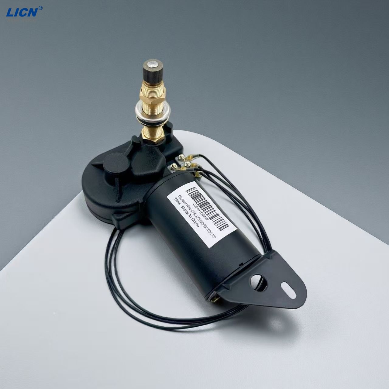
A: A speed reducer (or gearbox) is just the mechanical gear assembly. It requires you to mount a separate motor to it. A Reduction Gear Motor is an integrated unit where the motor and gearbox are coupled by the manufacturer. The integrated unit is usually more compact and eliminates engineering risks regarding fitment.
A: Overheating at low speeds is usually caused by two factors: "Copper Loss" from high current draw required to maintain torque, and the failure of the motor's internal cooling fan to generate airflow at low RPMs. If this occurs, check if your motor is rated for low-speed inverter use or consider up-sizing the motor.


